|
|
||||||||||||
|
||||||||||||
|
Research field: Power Conditioning Systems |
||||||||||||
|
|
|
|
|
|||||||||
|
"...many lacks of the electric energy distribution network may be solved by the use of state of the art power electronics and energy conversion systems...." |
||||||||||||
| WHY ACTIVE FILTER? | ||||||||||||
|
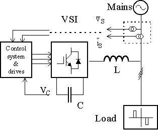
High power non-linear loads, such as ac/dc rectifiers, cause undesirable phenomena in the operation of power systems like harmonic pollution and reactive power demand. Parallel active filters have been recognized as a viable solution to current harmonic and reactive power compensation. Various active power filter configurations and control strategies have been proposed and developed in the last decade in order to reduce these undesirable phenomena. |
||||||||||||
| HOW DOES IT WORK? | ||||||||||||
|
|
||||||||||||
|
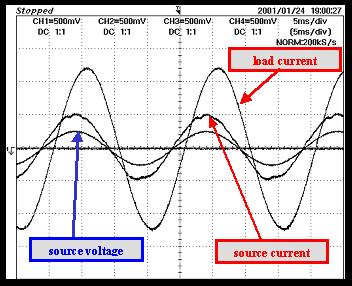
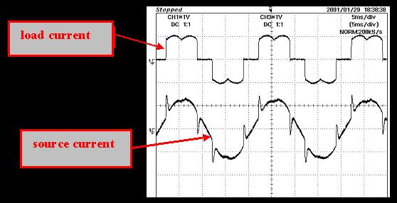
The principle of operation is based on the use of a power electronic structure capable to inject towards the mains the reactive and harmonic current required by the loads. According to their principle of operation, the parallel active filters behave as harmonics current source, leading the source currents to be sinusoidal and in phase with the corresponding voltages, whatever it is the load current absorption.
The compensation of harmonic current and reactive power can be obtained by using different solutions for the filtering algorithm. These algorithms generates the reference currents the filter has to inject, then the filtering performance as harmonic compensator are given by using high speed, high precision current regulators. The filter inverter absorbs a small amount of active power from the grid, that corresponds to the losses in the static switches and in the passive components (dc-link capacitor, ac-link inductors). |
||||||||||||
|
|
||||||||||||
|
WHAT DO WE DO? |
||||||||||||
|
|
||||||||||||
|
Our team has developed several active power filter configurations. These systems are characterized by the use of very simple algorithms, that can work properly also by measuring only one current system (source or load). The current compensation algorithm is based on the tracking of sinusoidal and balanced waveforms reference for the source currents whatever it is the load currents. These techniques don't require the computation of the harmonic contents of the load current, so they are simpler than other techniques have been proposed and can be implemented on low powerful, low cost microprocessors. In the proposed structure a regulator has the task to generate the reference value of the amplitude of the active current demanded by the mains. This is the value that yields to zero the error in the dc link voltage level. Then a high speed, high precision current regulation has been implemented for the control of the source current Space Vector Modulation (SVM). This current regulator is based on the use of the Space Vector Modulation (SVM), in order to minimize the ripple superimposed on the source current and voltage. This algorithm employs a reduced number of voltage and current transducers, contributing to reduce the cost of the system. Numerical simulations, carried out on four different configurations of APF, have shown that the performance of the developed, simplified structure of APF are quite similar to that of standard configurations. An experimental set up has been has been realized for the configuration that requires the measurement of only two source currents and of the dc-link voltage. |
||||||||||||
|
||||||||||||
|
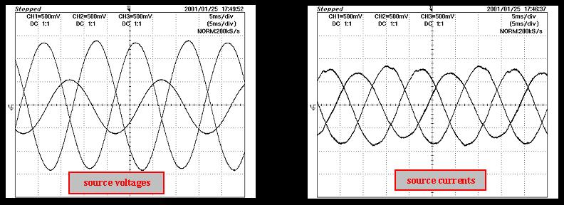
The proposed active filter works properly also in the case of voltage non idealities, like the voltage unbalance and the low order harmonic distortion. A reliable Three Phase Locked Loop (TPLL) recognizes the fundamental positive sequence of the source voltage also in the worst cases of voltage harmonic distortion. Under these conditions the APF absorbs sinusoidal and balanced currents from the source, that are in phase with the corresponding fundamental positive sequence component of the source voltages. |
||||||||||||
|
|
||||||||||||
|
The developed regulation structure for active power filter can be usefully employed in combination with other structures connected to the dc link bus. These structures are static converters capable to exchange active power between an energy storage device or an energy source and the dc-link. Throughout the inverter this active power can be easily transferred to the grid. |
||||||||||||
|
|
||||||||||||
|
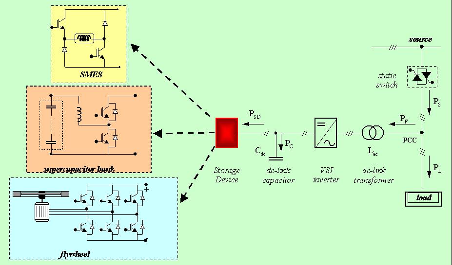
A Power Conditioning System (PCS) with energy storage capability can be considered a viable solution for improving the quality and the reliability of the electric energy supply. Several tasks can be performed at the same time, such as reactive power compensation, current harmonic reduction, and smoothing of pulsating loads. Moreover, the PCS can operate as Uninterruptible Power Supply (UPS) during short time interruptions of the grid supply. The proposed PCS is a flexible structure that can be coupled to several energy storage device like battery, flywheel, supercapacitor, Superconductive magnetic energy storage (SMES).
|
||||||||||||
|
Using new types of energy storage devices, such as superconducting magnets, flywheels or supercapacitors, which are more suitable for high power and low energy applications, it is possible to better exploit the energy reserve. The energy storage device is connected to a dc-dc converter allowing the bi-directional transfer of energy with the dc-link intermediate bus. The topology of the dc-dc chopper depends on the type of energy storage device. These new storage devices allow additional tasks to be performed using the same hardware structure required for the UPS operation. The additional tasks consist of reactive power compensation, current harmonic reduction, load unbalance compensation, and smoothing of pulsating loads. In this way, the UPS behaves as a Power Conditioning System (PCS) when the grid supply is present, improving significantly the power quality in the grid section next to the Point of Common Coupling (PCC).
|
||||||||||||
|
|
||||||||||||
|
|
||||||||||||
|
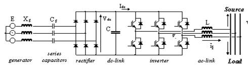
Power conditioning systems suitable to be used in conjunction with an energy source can be derived from the basic structure of an Active Power Filter and its control system. Two configurations of PCS have been developed in order to allow the energy transfer from an advanced generation systems to the grid: |
||||||||||||
|
·
New
Cogeneration System |
||||||||||||
|
|
||||||||||||
|
NEW COGENERATION SYSTEM |
||||||||||||
|
|
||||||||||||
|
||||||||||||
|
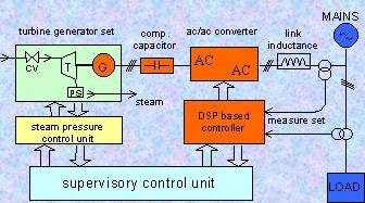
The pressure reduction is associated with a waste of entropy which can be saved by the system described. Examples for applications where pressure reduction is frequently needed are chemical and food processing plants and hospitals where low pressure steam is used for sterilization besides central heating. A special feature of a turbine using a relatively low pressure working medium is the need of high speed operation. Thus a high speed (12,000 rpm) permanent magnet, three-phase synchronous generator, is direct connected to the turbine shaft. The electric energy produced can be fed back into the existing utility mains by an ac/ac power converter. The converter system is composed by a three-phase diode rectifier supplying the dc link of a voltage source inverter. The parallel connection to the ac line is made trough a three-phase link reactor. |
||||||||||||
|
|
||||||||||||
|
The aim of this work is the analysis of a control algorithm for the electric power conditioner of the co-generation system, which could be implemented on a DSP based controller. The features of this controller are:
·
possibility to
use the power conditioning system for additional tasks
The main feature of this structure of power conditioning system is its possibility to behave as an active filter, i.e. compensation of reactive power and current harmonics of non-linear loads connected to the same mains. This possibility comes out looking at the structure of the dc/ac conversion system, which is similar to that of an active filter. In order to compensate reactive power and current harmonic in addition to the rated active power, the dc/ac converter has to be oversized. This additional investment cost is justified thanks to the good performances obtained by the active filter. |
||||||||||||
|
|
||||||||||||
|
PHOTOVOLTAIC PANELS |
||||||||||||
|
|
||||||||||||
|
Photovoltaic technology is the most promising candidate for the large scale spreading of renewable energy source. In order to contribute to lower the cost of new installation of photovoltaic panels, the activity research of our group has been targeted to the developed of very simple power electronic conversion structure for the transfer of the photovoltaic energy to the grid. We have developed two structures of power conditioning systems for PV panels
·
A three
phase, single-stage converter, suitable for large photovoltaic power
plants. |
||||||||||||
|
|
||||||||||||
| THREE PHASE, SINGLE-STAGE CONVERTER | ||||||||||||
|
|
||||||||||||
|
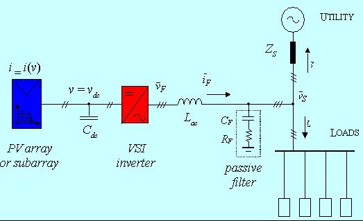
The Photovoltaic sources are combined with the structure of a power active filters in order to regulate both the active and the reactive power injected into the mains. In this way, the system is able to compensate undesired load characteristics such as phase unbalances, power flickers, and low-order current harmonics, improving the power quality.
|
||||||||||||
|
|
||||||||||||
|
SINGLE-PHASE, SINGLE-STAGE CONVERTER |
||||||||||||
|
|
||||||||||||
|
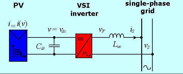
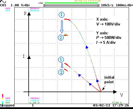
A new maximum power point tracking algorithm for single-stage converters connecting photovoltaic panels to a single-phase grid has been developed. The algorithm is based on the analysis of the current and voltage low-frequency oscillations introduced in the PV panels by the single-phase utility grid. The proposed control technique allows the generation of sinusoidal grid currents with unity power factor. The algorithm has been developed to allow an array of PV modules to be connected to the grid by using a single-stage converter. This simple structure yields higher efficiency and reliability when compared with standard solutions based on double-stage converters configuration. The converter has been developed for the installation on very small PV generation systems like photovoltaic roofs that now give an important share of new installations of PV panels. |
||||||||||||
|
||||||||||||
|
For further information about power conditioning systems, please feel free to contact |
||||||||||||
|
|
|
|
|
|||||||||