|
|
|||||||||||
|
|||||||||||
|
|
|||||||||||
|
Research field: Static Conversion |
|||||||||||
|
|
|||||||||||
|
|
|||||||||||
|
|
|||||||||||
INTRODUCTION |
|||||||||||
|
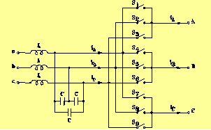
Adjustable speed drives of AC induction motors have received a large interest in industrial applications. These drives are usually based on indirect power conversion scheme using PWM AC-DC-AC converters. As it is known, the indirect power converters require a capacitor in the DC-link for energy storage. The matrix converters perform the power conversion directly from AC to AC without any intermediate DC-link. ADVANTAGES OF MATRIX CONVERTER The lack of reactive components in the DC-link is one of the salient advantages of the matrix converter, which allows a compact design. Furthermore, the matrix converter provides four-quadrant operation, sinusoidal input currents and controllable input power factor. So, the direct three-phase to three-phase converter have received considerable attention because they may become a good alternative to indirect converters. DISADVANTAGES OF MATRIX CONVERTERThe main disadvantages of matrix converters are the inherent restriction to the voltage transfer ratio of 0.866, a more complex control scheme and the need of nine bi-directional power switches. Due to the lack of internal energy storage the matrix converter will also be sensitive to disturbances in the input voltages, as these will couple directly to the output side of the converter.
Among these, only 21 are employed in Space Vector Modulation. The first 18 switching configurations have the common feature of connecting two output phases to the same input phase (active configurations). The last 3 switching configurations determine zero input current and output voltage vectors (zero configurations). The remaining 6 switching configurations have the three output phases connected to a different input phase (synchronous configurations). In this case the output voltage and input current vectors are rotating in space and cannot be usefully used to synthesise both the reference vectors. |
|||||||||||
|
|
|||||||||||
SPACE VECTOR MODULATION TECHNIQUE |
|||||||||||
|
|
|||||||||||
|
Applying the space vector modulation it is possible to generate any output voltage vector with a degree of freedom, that is the phase angle of the input current vector with respect to the input voltage vector. In principle, the SVM algorithm is based on the selection of 4 active configurations that are applied for suitable time intervals within each cycle period. The zero configurations are applied to complete the cycle period. |
|||||||||||
|
|
|||||||||||
ORIGINAL CONTRIBUTION FOR THE RESEARCH GROUP |
|||||||||||
|
|
|||||||||||
|
Ø Formulation of the SVM technique trough a direct approach The proposed SVM algorithm is different from that utilized by many researchers, where the conversion process has been fictitiously divided into stages: rectification and inversion, by introducing an imaginary DC-link. The proposed modulation performs the power conversion directly from AC to AC, allowing an easy comprehension of the theory, and leading to simple final equations. Ø Analysis of matrix converter performance with unbalanced and/or non-sinusoidal supply voltages A mathematical model of the matrix converter, which allows the analytical determination of the input currents under non-ideal supply voltages, has been proposed. The model is based on assuming ideal switches, and representing any variable with its mean value within a switching cycle. Writing the power balance equation between input and output sides of the matrix converter, it is possible to determine the relationships for the input currents for given input voltages. Ø Reduction of the input current harmonic content by using three new input current modulation strategies Matrix converters allow the output power control with a degree of freedom, which can be used to define different input current modulation strategies. The degree of freedom can be exploited in order to improve the performance of the matrix converter in terms of input current quality, in the case of unbalanced and non-sinusoidal input voltages. Three current modulation strategies for matrix converters have been proposed. The first one is based on keeping the input current vector in phase with the output voltage vector, the second one operates a dynamic modulation of the input current phase angle, and the third one keeps the input current vector in phase with the positive sequence fundamental component of the input voltage vector. Each modulation strategy has different characteristics and should be employed depending on the input voltage distortion type. Ø Analysis of the stability of matrix converters The stability of an electrical drive fed by a three-phase to three-phase matrix converter has been analyzed considering two different input filter structures. A state average model of the whole system, assuming a constant power load, is proposed. The stability of the system is evaluated by analyzing the migration of eigenvalues of the system, which is linearized around the operating point. The analytical approach allows the determination of relationships showing the maximum output power of the matrix converter as function of the parameters of power supply and input filter, emphasizing the improvement of the power limit achievable by using an input filter with damping resistance. Ø Methods for improving the matrix converter stability It is possible to compensate the negative effects generated by input voltage disturbances by monitoring the input voltages of the matrix converter and, consequently, calculating the duty-cycles necessary to generate balanced and sinusoidal output voltages on the basis of the instantaneous values of the input voltages. However, the compensation of the input voltage perturbations achieved by this control strategy might lead to instability phenomena when the matrix converter output power exceeds a maximum limit related to the parameters of power supply and input L-C filter. The power limit can be increased if the duty-cycles of the switching configurations are calculated applying a digital low-pass filter to the input voltages. Using this new control strategy, the capability of the matrix converter to compensate input voltage disturbances is affected to some extent, but the stability limits can be sensibly improved. Ø Definition of a new three-step commutation strategy In all commutation strategies based on either output current or input voltage sign measurement, the commutation instant of the output current between two bi-directional switches is inherently variable. This variability has to be taken into account and compensated when an optimum modulation of the matrix converter output voltages and input currents is desired. A new three-step commutation strategy has been proposed. This strategy relies on the measurement of both commutation voltage and output current sign. The advantage of the proposed new strategy compared to the others is that the commutation of the output current occurs always at the same instant with respect to the beginning of a switching commutation sequence. As a consequence, no compensation is required to the control DSP in order to get an optimum modulation of the input/output quantities. Furthermore, with respect to the four-step strategies, a faster commutation process is achieved, widening the linear operating region of the converter. Ø Comparison between matrix converters and back-to-back converters based on the thermal stress of the switches The comparison has been performed for different values of the output frequency, and assuming the same switches, i.e. IGBTs and diodes, and the same reactive components of the input filter. The aim of the comparison is the determination of the maximum output power that can be provided by the converters, taking into account the maximum thermal stress of the switching devices. The analysis emphasizes that the operating conditions for the matrix converter are critical when the output frequency is close to the input frequency. In this case the temperature distribution is not uniform for all the switches, being 6 IGBTs more stressed than the others. The thermal stress among the switches of the back-to-back converter output stage is more uniform compared to that of matrix converter. Furthermore, the maximum output power per switch that can be achieved with a matrix converter is lower than that of the back-to-back converter. However, the behaviour of the matrix converter shows a sensible improvement for lower output frequencies, showing good performance particularly at 0 Hz. In these operating conditions, the matrix converter is able to deliver high currents, whereas the back-to- back converter must be sensibly derated. This feature suggests that the matrix converter could be advantageously used in combination with electric drives, which usually require high currents at low speed. Ø Application of matrix converters for the implementation of DTC induction motor drives A new control method for matrix converters is proposed which allows, under the constraint of unity input power factor, the generation of the voltage vectors required to implement the direct torque control of induction machines. Using this control method it is possible to combine the advantages of matrix converters with the advantages of the DTC schemes. Numerical simulations and experimental tests have shown the effectiveness of the proposed control scheme in both steady-state and transient operating conditions. |
|||||||||||
|
|
|||||||||||
EXPERIMENTAL ACTIVITY |
|||||||||||
|
|
|||||||||||
|
1 - The experimental activity has been carried out within a co-operation of the DEPARTMENT OF ELECTRICAL ENGINEERING (University of Bologna) with AALBORG UNIVERSITY and DANFOSS COMPANY IN DENMARK. |
|||||||||||
|
|
|||||||||||
|
Characteristics of the experimental set-up |
|||||||||||
|
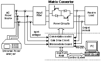
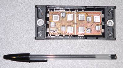
The power stage of the matrix converter is based upon three special designed power modules, realized with 1200V, 25A Siemens IGBT’s and fast recovery diodes. Each module contains three AC switches. Each AC switch is constituted by two anti-paralleled IGBT’s in common collector configuration with series diode. |
|
||||||||||
|
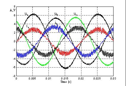
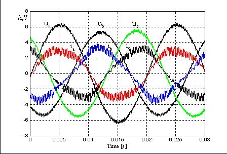
The prototype has been utilized for verifying the control algorithms developed by the Research Group of Bologna University, aimed to improve the matrix converter performance in case of non-ideal supply voltages. As an example, the following figures show the improvement of the input current quality achieved by using one of the proposed control techniques when the input voltages are unbalanced. |
|||||||||||
|
|||||||||||
|
|
|||||||||||
|
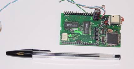
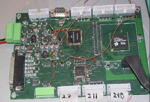
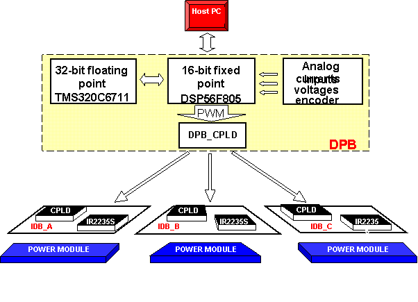
2 - A further experimental prototype has been realized within a co-operation of the DEPARTMENT OF ELECTRICAL ENGINEERING (University of Bologna) with PHASE COMPANY and IRCI COMPANY in Italy. |
|||||||||||
|
|
|||||||||||
|
|||||||||||
|
|
|||||||||||
|
|
|||||||||||
|
3 - A new co-operation has been recently established between the DEPARTMENT OF ELECTRICAL ENGINEERING (University of Bologna) and the SCHOOL OF ELECTRICAL AND ELECTRONIC ENGINEERING OF NOTTINGHAM (UK), for verifying by experimental tests the results obtained in terms of stability of matrix converters. |
|||||||||||
|
|
|||||||||||
|
|
|||||||||||
|
In recent years, the wide diffusion of induction motor drives fed by Voltage Source Inverter (VSI) and the increasing interest on matrix converter have encouraged a considerable search activity concerning the performance of several modulation techniques, in terms of current ripple, optimised switching sequence and increased voltage transfer ratio. Many authors have shown that Space Vector Modulation (SVM) usually offers better performance compared to regular sampled carrier based Pulse Width Modulation (PWM) technique. The basic principle of operation of SVM is to approximate the desised output voltage with a combination of the nearest admissible voltage vector, each of them is applied for a finite time interval. It has been clearly documented that a suitable placement and sequence of the voltage space vectors within the cycle period can lead to lower current ripple and higher voltage transfer ratio, compared to regual sempled carrier base PWM technique. Alternative modulation strategies are based on adding a third harmonic component to the common mode voltage, so that the position of the active space vectors varies only silghty compared to SVM technique.
|
|||||||||||
|
|||||||||||
|
|
|||||||||||
|
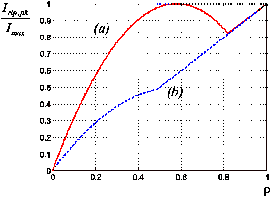
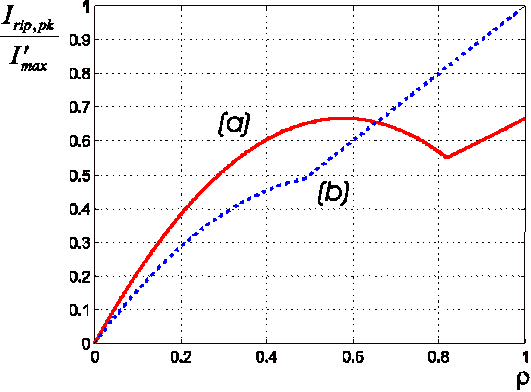
Ø The most common SVM stategies (two-phase modulation and symmetric modulation) have been compared with reference to the peak value of the current ripple. Ø The link existing between the common mode voltage and the placement of the zero voltage space vectors and by utilizing this degree of freedom to determine an optimal modulation technique has been documented in details. Ø A method for calculating the analytical expression of the common mode voltage that determines the minimum RMS value of the load current ripple in each cycle period is presented. The results of the analysis consist of very simple equations, which can de used in digital control systems for on-line implementation of the optimal modulation technique. Ø A new general and complete solution of the problem of the modulation strategy of three-phase matrix converters is presented. This solution has been obtained using the duty-cycle-space-vector (DCSV) approach, which consists of a representation of the switch state by space vectors. In this way, all the well-estabilished modulation stategies for matrix converter can be considered as a particular case of the proposed one. |
|||||||||||
|
|
|||||||||||
|
|
|||||||||||

